
For nickel cadmium batteries
What is IEC?
IEC standard stands for International Electrotechnical Commission and is the most important international electricity standard. IEC is actually an international electrotechnical commission affiliated with the ISO international standard organization.
This organization serves the global markets and society through the development of standards in the following cases:
- power industy
- Evaluation and compliance of products
- Installation and configuration method in all electrical and electronic technologies
IEC promotes global trade and economic growth and encourages the development of safe, efficient and environmentally friendly products, systems and services. Millions of devices dealing with electronics use IEC international standards and ISO conformity assessment systems.
1) IEC standard generalities
1-1 Purpose and scope of application:
The IEC standard specifies the nomenclature, design, dimensions, testing, and requirements for secondary nickel-cadmium single cells, multiphase.
Note: In this text, the word polyhedron refers to rectangular cells with a bottom.
If you haven’t read the full introduction article on nickel-cadmium batteries, you can learn more about nickel-cadmium batteries through this link.
1-2 Mandatory references:
The following mandatory documents include the provisions that, through the references in this text, constitute the provisions of the IEC international standard.
Existing standards:
- (486) IEC 60050: International Electrical Vocabulary, Chapter 486 Secondary Cells and Batteries
- IEC60410 : Sample plans and inspection procedure
- IEC60417: (all parts) Graphic symbols for equipment
- IEC60485: Electronic digital DC voltmeters and electronic analog to digital converters
- IEC61438: Safety and potential hazards in the use of secondary alkaline cells and batteries and a guide for equipment manufacturers and consumers
1-3 Definitions:
In this international standard, the definitions include (486) IEC 60050 and the following definitions.
1-3-1 Porous:
A secondary cell has a cap through which the produced gases can escape through a hole.
Note: The cell opening may be equipped with a vent system.
1-3-2 Nominal voltage:
The voltage of a rechargeable porous nickel-cadmium single cell is 1.2 volts.
1-3-3 Nominal capacity:
The capacity value C5Ah (ampere hours) declared by the manufacturer where a single cell can be discharged with a current of 0.2 ItA until reaching the final voltage V1 at 20°C after charging. The conditions of charging, storage and discharge are specified in paragraph 4.
1-3-4 tolerance of measuring parameters:
The overall accuracy of the measured values, corresponding to the actual or specified values, must be within the following tolerances.
A) ±1% for voltage
b) ±1% for current
c) 2 degrees Celsius for temperature
d) ±0.1% for time
e) ±1% for capacity
These tolerances include a combination of the accuracy of the measurement equipment, the measurement techniques used, and all other sources of error in the test procedure. Refer to IEC 60051 for analog equipment and IEC60485 for digital equipment for help in instrument selection. In addition, the details of the use of the tool should be mentioned in the results of the reports.
2) Naming and marking in IEC standard
2-1 Naming cells:
Secondary nickel-cadmium single cells, with polyhedral cross-sections, are identified by the letter K, followed by one of the letters L, M, H, or X as follows:
L : with a low discharge rate
M : with an average discharge rate
H : with a high discharge rate
X : with a very high discharge rate
Note: Usually, but not exclusively, this designation is for the following types of cells:
L : up to ItA 0.5
M : Up to ItA 3.5
H : up to ItA 7
X : Above ItA 7
After these two letters, the figures of the cell capacity come in ampere-hours, for example: 185 KH. For cells with a plastic body, the letter P must come after the numbers, for example P185 KH
2-2 Terminalizing the cells:
The IEC standard does not specify the terminals of the cells.
2-3 marking:
Each individual cell or block must be durably marked with at least the following information:
- Cell type (nomenclature is specified in section 1-2. Also, in addition, a manufacturer is allowed to use the nomenclature of her own models).
- The name or trademark of the manufacturer or supplier
- Positive terminal: It is indicated by a red washer or a prominent symbol (see the graphic symbols 5005 of the IEC60417 standard).
2-4 safety recommendations:
The manufacturer must provide recommendations for cell transport safety (see IEC61438).
3) Dimensions in IEC standard
Note 1: Metal body cells may have 2 or more terminals and 4 or more knobs.
Note 2: Plastic body cells may have 2 or more terminals and no handles
2-2 Terminalizing the cells:
The IEC standard does not specify the terminals of the cells.
2-3 marking:
Each individual cell or block must be durably marked with at least the following information:
- Cell type (nomenclature is specified in section 1-2. Also, in addition, a manufacturer is allowed to use the nomenclature of her own models).
- The name or trademark of the manufacturer or supplier
- Positive terminal: It is marked by a red washer or a prominent symbol (see graphic symbols 5005 of IEC standard No. 60417).
2-4 safety recommendations:
The manufacturer must provide recommendations for cell transport safety (see IEC61438).
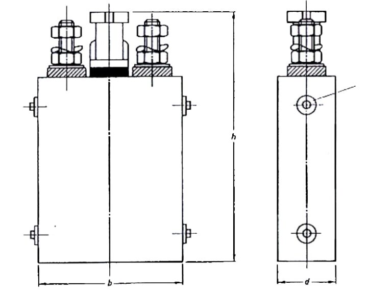
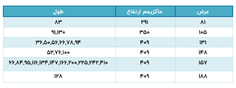
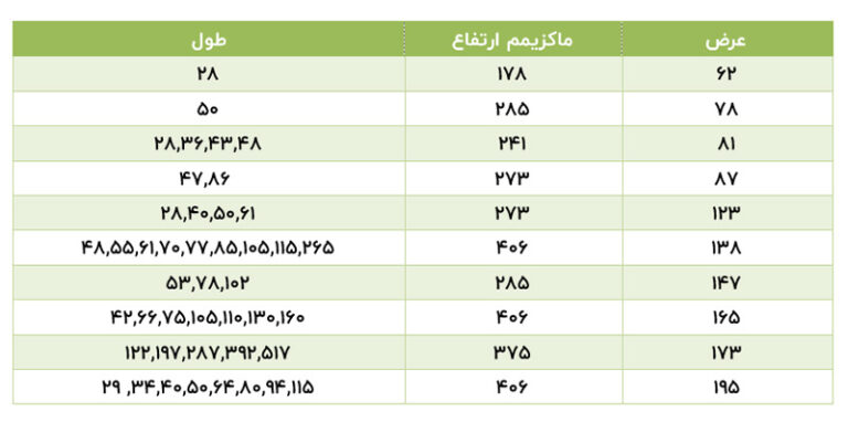
Note 1: The values given in Tables 1(A) and 1(B) are preferred values.
Note 2: The width is related to the overall dimensions of the cell except for the width of the handles.
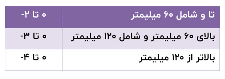
The value of width and length given in Tables 1(A) and 1(B) is its maximum value and its decreasing tolerance value is given in Table 2.
Note 3: The height value given in table a1 and b1 corresponds to the maximum height up to the top of the terminals or the closed cell cap, whichever was greater.
Note 4: The values given in table a1 and b1 do not depend on the cell capacity; They are accepted for all types and quantities of L, M, H or X rectangular nickel cadmium porous batteries.
4) Electrical tests in IEC standard
The charge and discharge currents for testing must be in accordance with 4.1 to 4.9 and based on the nominal cell capacity values.
4-1 Charging procedure for testing purposes:
Before charging, the cells should be discharged at a temperature of 20 ± 5 °C with a constant current of ItA 0.2 to a final voltage of 1 V. Charging before all types of discharge tests should be done based on the ambient temperature of 20 ± 5 °C and with a constant current of 0.2 ItA during a period of 7 to 8 hours, except in the cases specified in this standard.
4-2 Drain function:
The following discharge tests should be performed in order and all cells should be tested at +20, +5 and -18 degrees Celsius.
4-2-1 Discharge performance at20°C span:
The cells should be charged according to section 1-4 and after charging, the cells should be kept for a minimum of 1 hour and a maximum of 4 hours at an ambient temperature of 20 ± 5°C and then discharged according to table 3, the discharge time should not exceed the specified minimums. in table 3 is less.
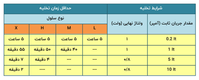
A: It is allowed to perform this test up to 5 times; However, if we get the desired results at the end of the first test, we can stop the test.
b: strong Before testing ItA 5 and ItA 10, apply a conditioning cycle if needed, this cycle includes charging and discharging at ItA 0.2 based on 4-1 and 4-2-1.
4-2-2 : Discharge performance at C° 5:
The cell should be charged according to Section 1-4. After charging, it should be kept at an ambient temperature of 2 ± 5°C for 24 hours. This action is to ensure that the temperature of the electrolyte reaches 2 ± 5°C during 24 hours. Then it should be discharged at the same ambient temperature according to the specifications of Table 4. The discharge flow time should not be less than the minimum value specified in table 4.
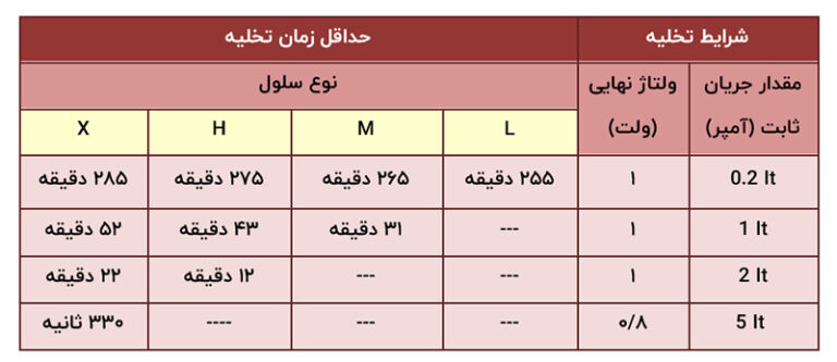
Before the discharge test ItA 2 and ItA 5, a conditioning cycle can be performed if needed. This cycle includes charging and discharging at an ambient temperature of 5 ± 20°C with an ItA current of 0.2 according to section 1-4 and environment 1-2-4.
4-2-3 Discharge performance at -18°C:
The cell should be charged according to section 1-4, after charging, the cell should be kept at an ambient temperature of -18 ± 2°C for 24 hours. This action is to ensure that the temperature of the electrolyte reaches -18 ± 2°C during 24 hours. After that, it should be discharged at the same ambient temperature according to the specifications of Table 5. Discharge times should not be less than the minimum value specified in Table 5.
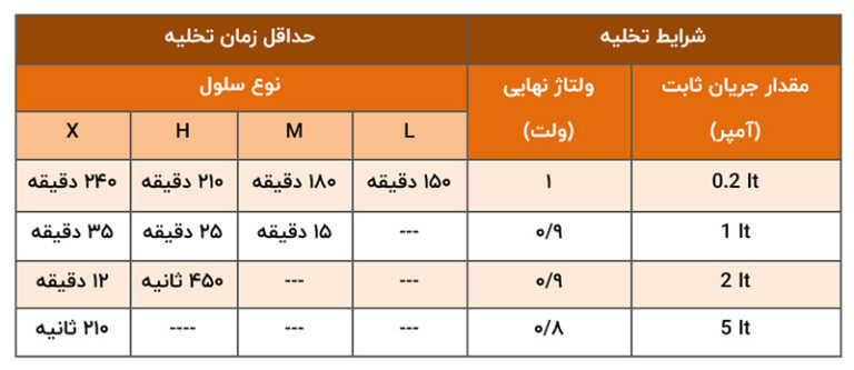
Before the ItA 2 and ItA 5 discharge test, a conditioning cycle may be performed if needed. This cycle includes charging and discharging with ItA 0.2 at an ambient temperature of 5 ± 20°C according to section 4-1 and 4-2-1.
4-2-4 high current test:
This test is to check the ability of the cell to withstand high currents.
4-2-4-1 Test method:
Cells should be charged according to Section 4.1. After charging, the cells should be kept at an ambient temperature of 5 ± 20 °C for at least 1 hour and at most 4 hours. Then they should be discharged at the same ambient temperature for 5 seconds and based on the currents given in Table 6. At the time of discharge, the voltage of the battery terminals must be recorded.

4-2-4-2 Acceptance criteria:
No deformation and melting in the cell body or deformation in the cell components should be observed. Also, the voltage of the cells during discharge should not have any interruption.
4-3 Charge survival in IEC standard:
Charge maintenance is tested according to the following method.
After charging according to section 4-1, the cell should be kept in open circuit condition for 28 days. The average temperature of the environment during the period should be 20 ± 2°C. The ambient temperature can be within the range of 20 ± 5°C in a short period. Then they should be discharged according to the conditions specified in section 4-2-1 and ItA current 0.2. The duration of evacuation should not be less than 4 hours.
4.4 Stability:
4-4-1 Stability in cycle mode:
4-4-1-1 Test conditions:
The stability test in the IEC standard must be performed at an ambient temperature of 20 ± 5 °C, and the electrolyte temperature must be prevented from increasing above 40 °C during the test, for example, if necessary, by providing air conditioning equipment. Did.
In order to prevent the reduction of the electrolyte level, it is possible to add distilled water or hardened water to the cell during the test, based on the manufacturer’s recommendation.
Replace the electrolyte at any time if the specifications of the electrolyte are inconsistent with the manufacturer’s recommendations.
The cell should be prepared according to section 4-1.
4-4-1-2 cycle 1 to 50:
The cycle must be performed according to the conditions specified in Table 7. Charging and discharging are performed on a constant current basis.
Performing the cycle except the 49th and 50th cycle in order to start the next fifty cycles, must be continuous.
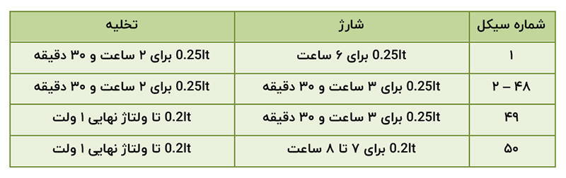
4-4-1-3 Acceptance conditions:
Cycles 1 to 50 should be repeated until the length of discharge in each fiftieth cycle is less than 3 hours and 30 minutes. At this stage, one more cycle is performed according to section 4-2-1 with ItA 0.2. The intended stability test will be completed when the discharge time is less than 3 hours and 30 minutes in two consecutive cycles. The number of cycles when the complete test is accepted should not be less than 500 cycles.
4-4-2 Permanent charge stability:
The IEC standard does not specify a constant charge stability test.
The cell must be evacuated according to Section 4-1.
The cell should be charged with constant voltage according to the specifications of Table 8.
4-5 Acceptance of charge in constant voltage mode:
The cell must be evacuated according to Section 4-1. The cell should be charged with constant voltage according to the specifications of Table 8.
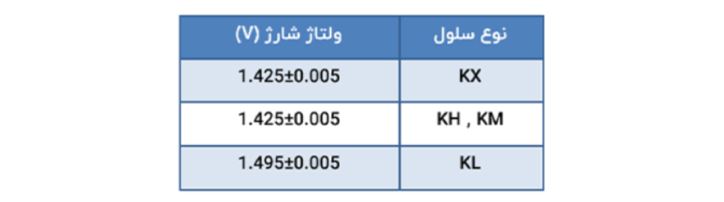
The charging current should be limited to 0.2 ItA. The temperature should be 5 ± 20 C and the charging time should be 24 hours. According to the IEC standard, after charging, the cell must be kept at an ambient temperature of 5 ± 20°C for a minimum of 1 hour and a maximum of 4 hours, and then the cell is discharged according to the conditions of section 4-2-1 with ItA 0.2. The duration should not be less than 4 hours.
4-6 Overcharge:
The IEC standard does not specify an overcharge test.
4-7 Function in cell cover:
The IEC standard does not specify the performance of the cell cover.
4-8 electrolyte survival test:
During charging, gas is produced inside the cell and the electrolyte will be sprayed into the air along with the gas, which leads to the reduction of the electrolyte. To prevent this reduction, screens are placed in the cell or in the capping system to block the cell.
This test is to evaluate the cell’s ability to prevent electrolyte depletion.
4-8-1 Test procedure:
Before performing the test, the electrolyte level should be set to its maximum level according to the manufacturer’s guide, the cell should be charged according to section 4-1. Charging should continue at a constant current of ItA 0.05 for 2 hours.
Gases coming out of the cap (vent) during 2 hours of additional charging must pass into 3 bottles which are connected in series and each container contains 1.200 mol per liter of sulfuric acid. After this period, the amount of potassium hydroxide absorbed in sulfuric acid should be measured.
4-8-2 Conditional:
The total amount of potassium hydroxide measured should not exceed 0.05 mg/Ah.
4-9 her warehouse:
Prepare the cell for maintenance according to the manufacturer’s instructions. The cell should then be kept for 12 months at an average temperature of 5 ± 20°C and 65 ± 20% humidity. During storage, the ambient temperature should not exceed 5 ± 20°C.
After the storage time, the cell should be prepared for use according to the manufacturer’s instructions. The cell should then be tested according to section 4-2-1 and cover all the specifications stated therein.
4-9-1 Mechanical tests:
Mechanical tests should be designed in relation to the intended application. This standard does not specify the mechanical tests that are based on the agreement of the buyer and the manufacturer.
4-9-2 Physical appearance:
Visual inspection should be done on the cells, its appearance should be without cracking, damage or corrosion, any deformation should be within the tolerance range of dimensions specified by the manufacturer.
5) Conditions for approval and acceptance of IEC standard
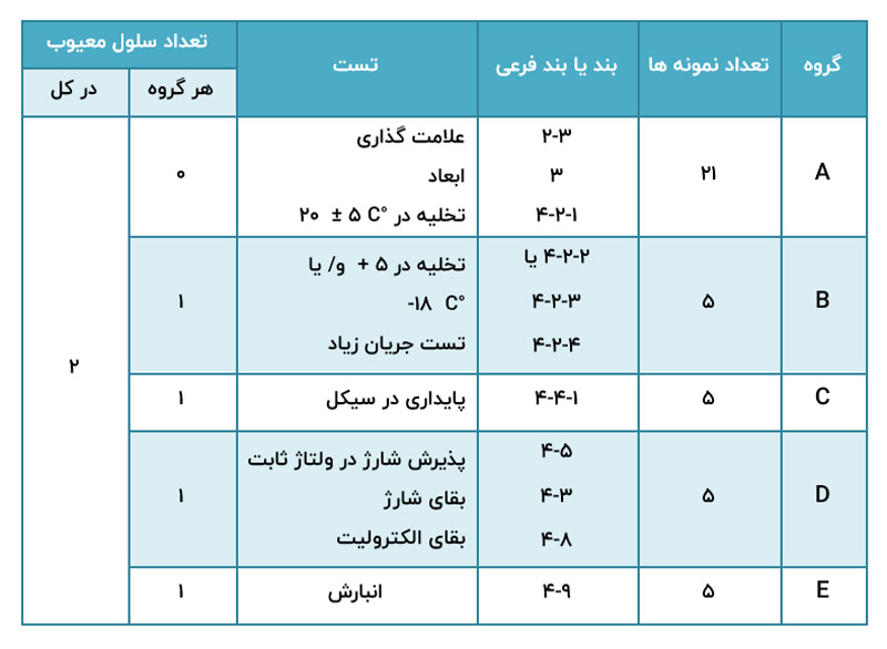
5-1 Type Approval:
For type approval, the samples and test procedure are given in Table 9, the total number of cells required for type approval is 21, the cells used for testing must be new.
All cells under test are placed in group A. After that, we randomly divide them into 4 groups of 5 cells, B, C, D, E, respectively. One remaining cell is used as a spare to repeat the test in case of an event outside the manufacturer’s responsibility. The test should be done for each group of cells.
The number of confirmed defective cells in each group and in total are listed in Table 9. (A cell is considered defective if it does not pass all or some of the tests of each group)
5-2 acceptance of the battery set:
These tests are performed for the delivery of single cells, unless otherwise agreed between the buyer and the seller. Inspection and tests based on inspection level and AQL (Approved Quality Level) are suggested in Table 10. The sampling method is based on IEC standard No. 60410.
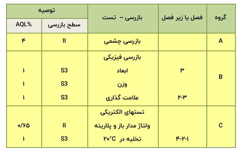
Note: 2 or more errors should not occur on 1 cell. Only the error corresponding to the lowest AQL is considered.